

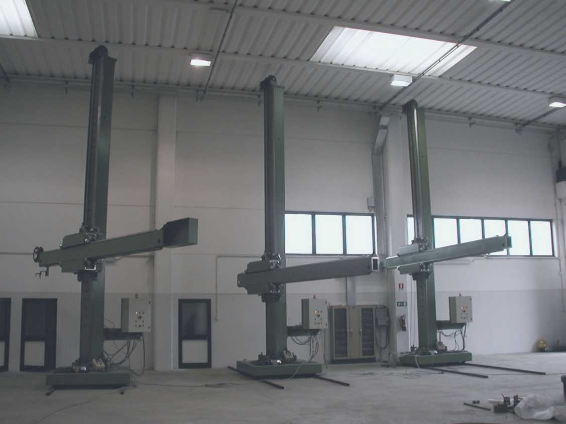
Capacity: 1.8 M × 0.7 M to 12 M × 12 M
12 M × 12 M COLUMN & BOOM
We understand that the Rotators and Column & Boom Manipulators may be used for cladding operations and we should mention that in these cases very slow movements are essential. We can incorporate in the “AMIN” traverse drive 2 speed gear box which enables the boom to be retracted very slowly, e.g.:
With these speeds it is possible to arrange for the boom to be retracted at very slow speed when spiral cladding, using either the strip method or the wire electrode method.
We have mentioned above that one way of overcoming this matter is by using a precision cross-roll bearing on which the column rotates. The design of the slide-ways and the very wide service area on which the supporting rollers traverse also helps. However, we have had very considerable experience in Column and Boom design and developed a method of fabrication which enables us to offer Columns and Booms with a much better deflection figure than any of our competitors. We do in fact build in five different designs in order to ensure that the Column and Boom is correct with controlled deflection relative to height, boom travel and weight to be carried.
Machine classifications:
“AMIN” Column & Boom Manipulators are built in five different designs. These groups cover a range of machines comprising 1/RMB up to Heavy Duty machine 1RC – 12 M × 12 M. The latter machine having 12 Mtr. maximum height under Boom and 12 Mtr. arc travel.
The recommendation as to the most suitable Manipulator to meet requirements depends upon:
Thus, a Column and Boom can have smaller dimensional proportions and yet be of more robust design than a Column and Boom which has a greater horizontal and vertical Boom travel.
The Manipulator comprises four essential components: Free Standing Base (or Travelling Carriage) – Column – Saddle – Boom
We have developed an extremely robust fabricated design which has a minimum depth to give the necessary rigidity. The base design is such that the machine is free standing when the Boom is being operated in the maximum height and fully extended. The Base can be either stationary or can be supported on four single flanged wheels to form a Traveling Carriage. Alternatively, two double flanged wheels and two plain wheels to travel along the track-way with either constant speed or variable speed drive.
The Column is supported on a cross-roll bearing (not a plain ball bearing). The larger machines are fitted with pre-loaded cross-roll bearings, which eliminate the “free-play” at this point, thus reducing Boom deflection. The diameter of the cross roll bearing ranges from 430 mm to 1660 mm. Clamps are provided so that when the welding head is in the correct position the Column can be manually securely located. Motorized Column rotation can be incorporated.
Get a customized quote or technical specifications from our experts.
Request Quote